Buying a refurbished sonde can save money, but only if it has been tested the right way. In HDD, the sonde is not an extra part it is the source of your locating data, and depth, pitch, roll, temperature, and signal stability all depend on it. This guide explains how refurbished sondes should be tested before sale in real shop conditions, so you can spot weak units early and avoid false savings.
What “refurbished sonde” should actually mean
A refurbished sonde is not just a used unit that was cleaned. It is a sonde that has been rebuilt and confirmed to meet working standards through a full process: it is inspected for physical damage, tested electrically, verified for correct functions (signal, pitch/roll, temperature, battery performance), and then validated under load so it can run reliably in real drilling conditions. If any of these steps are skipped, it is not refurbishment. It is simple resale.
Where refurbished sondes are used
Refurbished sondes are used in the same jobs as new sondes, when crews want reliable performance with lower upfront cost. Typical use cases include:
- Horizontal Directional Drilling (HDD)
for utility installs and replacements
Gas lines, water, sewer, electrical, telecom, and fiber in urban corridors and crossings. - Interference-heavy work
Areas with power lines, rebar, steel casing, railways, and dense underground utilities where stable signal matters. - Contractor fleets and backup units
Crews often keep refurbished sondes as secondary units, spare frequency options, or backup gear for tight schedules. - Short-to-medium projects and multi-rig operations
When multiple rigs need compatible transmitters and downtime is costly, refurbished units help scale inventory without buying everything new.
Step 1. Visual and mechanical inspection
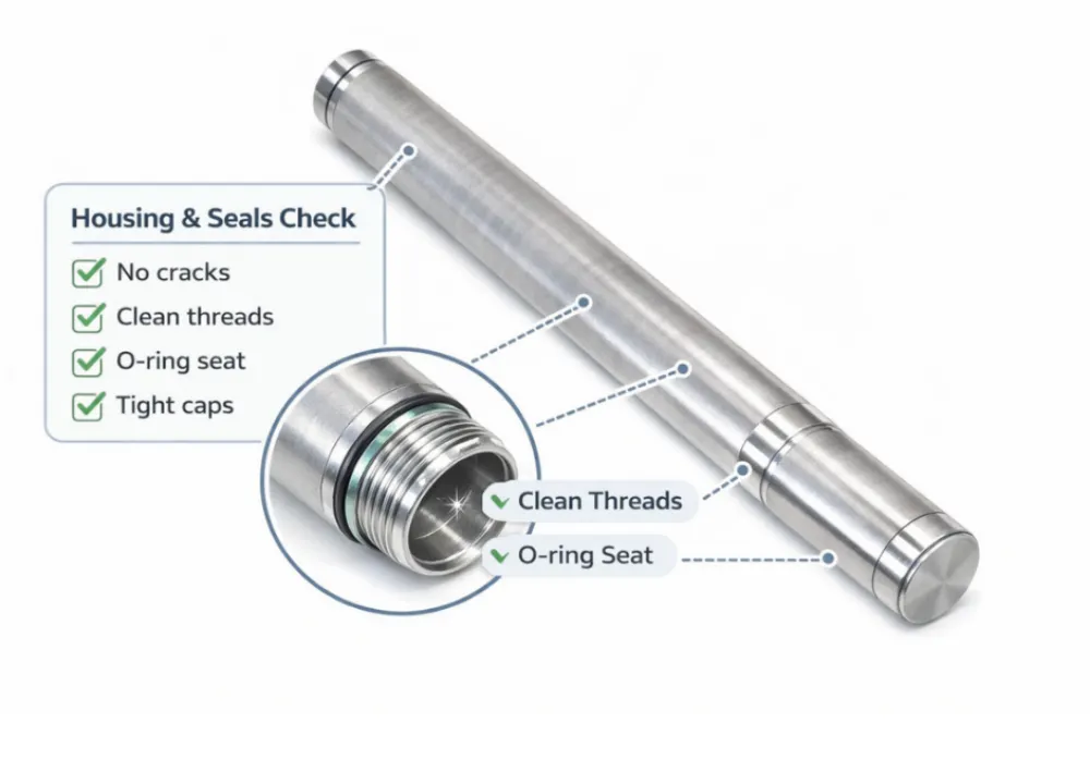
Testing starts with the sonde body. Not with electronics. If the housing is compromised, everything inside is at risk. A clean signal today does not matter if moisture gets in tomorrow.
First, the technician checks the housing for structural damage. Look for cracks, chips, and deep scratches. Pay special attention to impact zones and edges. Even small fractures can become leak paths under vibration and pressure.
Next, threads are inspected. Threads must be clean and sharp, with no flattening or cross-threading. Damaged threads do not just make assembly harder. They prevent the end cap from sealing correctly and they increase the chance of water ingress.
Then the battery cap area and the O-ring seat are checked. The O-ring seat must be smooth and intact. There should be no deformation and no corrosion. Any corrosion here is a warning sign, because it often means the sonde has already been exposed to moisture.
Finally, end caps and seals are checked for fit. They must seat tightly with no wobble. Loose seating is a mechanical failure waiting to happen, especially during long bores and repeated handling.
This step matters because water ingress kills sondes slowly. A sonde can look “fine” on a bench test and still fail after one bore. A proper refurbishment does not try to “patch” compromised housings. Units with damaged sealing surfaces are rejected and removed from circulation.
Step 2. Internal inspection and cleaning
After the visual and mechanical check, the sonde is opened. This is where you find the problems that do not show up on the outside. A housing can look clean while the inside has corrosion starting on contacts or contamination on the board.
Inside, the technician removes the internal boards. This is done carefully to avoid stressing connectors or damaging components. The goal is not just to “look inside.” The goal is to inspect every point that can cause intermittent failure later.
Next, all contacts are inspected. Look for discoloration, oxidation, pitting, or looseness. Contacts that look slightly dull can still create voltage drops under load. That leads to signal instability, random shutdowns, or weak transmission range.
Corrosion is then checked under magnification. This is important because early-stage corrosion can be hard to see with the naked eye. It often starts around solder joints, connector pins, and edges where moisture sits. If corrosion is present, a good shop does not ignore it. They identify the cause and decide if the unit can be reliably restored.
Then residue from drilling fluids is removed. Drilling mud and fine particles can leave conductive or corrosive films over time. Even if the sonde still works, residue increases the risk of sensor drift and electrical leakage, especially in humid environments.
There are no shortcuts in this step. Proper cleaning uses approved solvents, anti-static tools, and controlled drying. Drying is not “leave it on the bench.” It is done to a standard so moisture does not remain trapped in seams or under components.
If the seller describes this step as “we wiped it down,” that is not refurbishment. It is cosmetic cleaning. For HDD equipment, that difference shows up in the field.
Step 3. Battery system testing
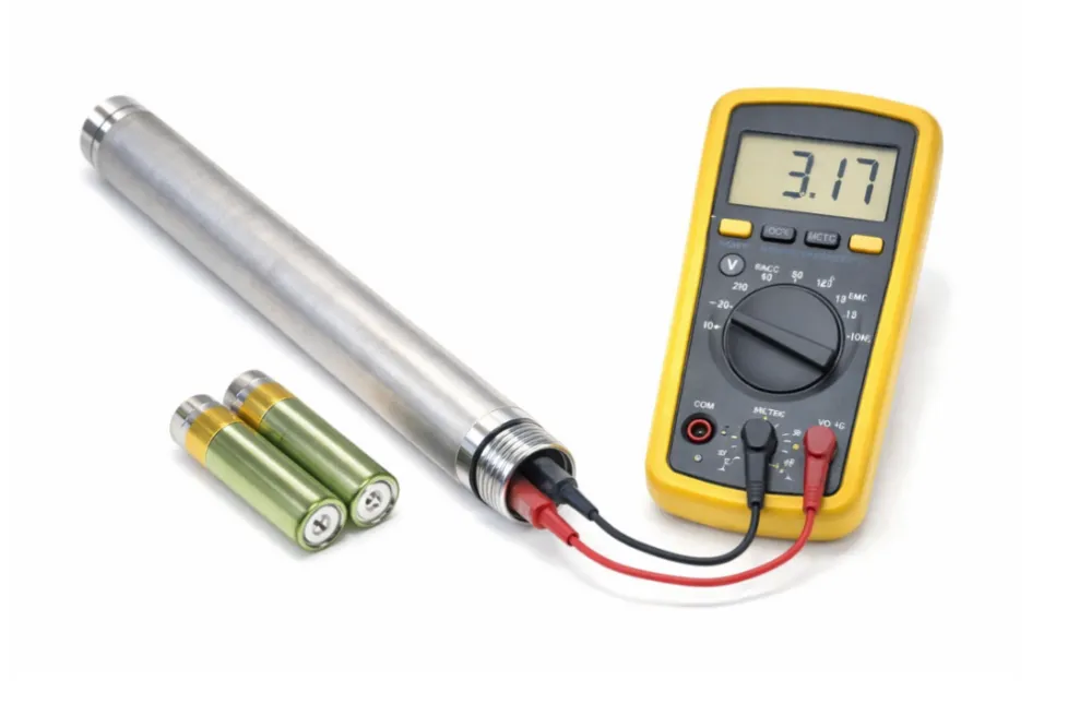
Many sonde failures start with power instability. The unit may look fine on the bench. It may even transmit. But once it is under real load, voltage drops and the signal becomes unstable.
First, the technician checks the battery contacts. Contacts must be clean, with no oxidation or discoloration. Springs must hold firm tension. If springs are weak or contacts are loose, the sonde can lose power for a split second. In HDD, a split second is enough to lose signal lock or get bad readings.
Next, voltage is tested under load. Idle voltage is not a real test. Almost any battery can show “good” voltage with no demand. The shop applies a controlled load and measures how the system behaves when current draw increases.
Then power drop during transmission is measured. This is the key point. The sonde consumes more power when it is actively transmitting. A weak battery system will show a noticeable voltage sag. That sag leads to reduced locate range, inconsistent data, or unexpected shutdowns.
A sonde that only passes idle voltage checks is not proven. Proper battery testing simulates real operating conditions, because that is where failures happen.
Step 4. Frequency verification
Before you buy a DigiTrak transmitter, make sure its frequency matches your locator and your typical jobsite requirements.
Every sonde is built for a specific frequency, and that frequency must be exact. In HDD, “close enough” is not a standard. If the transmitter is off-frequency, the locator may still pick it up, but performance drops and readings become less trustworthy.
Frequency is checked against calibrated reference equipment. This is not a guess based on what the locator shows on screen. A proper shop measures the output directly and confirms it matches the specified frequency within tight tolerance.
Then the frequency is verified across the operating temperature range. Electronics behave differently when they warm up. A sonde that is accurate at room temperature can drift after it runs for a while, especially in long bores or hot conditions.
Finally, drift is checked during continuous transmission. The unit is run for an extended period and monitored for stability. This step catches intermittent issues and components that shift as they heat.
This matters because even small frequency drift can cause reduced locate range, unstable depth readings, and incorrect roll or pitch values. Those problems are hard to diagnose in the field, because they look like interference or operator error. If a seller says the frequency is “close enough,” the sonde is not ready for real work.
Step 5. Signal strength and stability testing
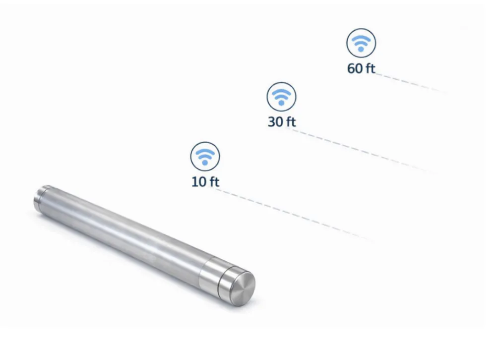
Signal power alone is not enough. A sonde can transmit a strong signal and still be unreliable. What matters in HDD is stability. The locator needs a clean, consistent signal to calculate depth and orientation correctly.
First, peak signal strength is measured. This confirms the sonde can produce the expected output and has no obvious transmission weakness. But this is only the starting point.
Next, signal consistency is checked over time. The sonde is run continuously while the technician monitors the signal for dips, spikes, or sudden changes. Intermittent instability is a common problem in used units. It may show up only after the sonde warms up or after it has been transmitting for a while.
Noise behavior is also tested in both idle and active states. Some sondes create extra noise when they switch modes or when sensors update. That noise can reduce locate reliability, especially in interference-heavy corridors.
Testing is done at multiple distances, not just close-range. A sonde can look “fine” up close and still lose stability at realistic working distances. It is also tested through controlled interference. The goal is not to prove the sonde can beat every jobsite condition. The goal is to confirm it behaves predictably when noise is present.
Finally, the test runs over extended runtime. Short tests miss heat-related issues and intermittent faults. A good refurbished sonde holds signal without spikes or drops, and it stays consistent from start to finish.
Step 6. Pitch and roll accuracy
Pitch and roll errors are not a small defect. They change how the crew steers the bore. They affect the planned depth profile, the exit point, and clearance from other utilities. If the sonde lies about pitch or roll, the job can drift off plan without anyone noticing early enough.
Accuracy is verified using a calibrated fixture. The sonde is mounted so it cannot shift during measurement. This removes human error and makes the test repeatable. A shop that “checks it by hand” cannot claim real calibration.
Known pitch angles are then applied. The technician sets specific angles on the fixture and records the sonde’s reported values. The same approach is used for roll orientation, with controlled rotations and fixed reference points.
Readings are compared to reference values. The acceptable deviation is tight. The goal is not “it’s close.” The goal is “it matches the standard.” If the sonde is consistently off, or if it jumps between values, it is rejected.
No software tweak can fix bad sensors. If pitch and roll are wrong, the hardware is wrong. A proper refurbishment does not ship that unit.
Step 7. Temperature sensor validation
Temperature readings are often ignored, but they should not be. The temperature sensor is not just a “nice to have” field on the screen. It is a health indicator for the sonde during operation.
Temperature matters because overheating usually means internal stress. It can point to power issues, component degradation, or poor internal contact. Sudden temperature spikes are also a warning sign. They often correlate with battery problems, unstable transmission load, or faults on the board.
Testing starts with an ambient temperature check. The technician verifies the sonde reports a reasonable value at room conditions and does not show obvious offset. This is a quick way to catch sensor failures or bad calibration.
Next, warm-up behavior is monitored. The sonde is turned on and allowed to run while the shop watches how temperature changes during normal operation. A healthy unit warms gradually and predictably. A problematic unit may climb too fast or jump in steps.
Finally, stability is checked during extended transmission. This is where hidden issues show up. Some sondes behave normally for a few minutes, then heat builds and instability starts. A good refurbished sonde stays within a normal temperature range and reports consistent readings over time.
A sonde that heats up abnormally will fail sooner. Even if it still “works,” it becomes a risk you do not need on a real bore.
Step 8. Compatibility testing with locators
A refurbished sonde must be tested with real locators, not only with bench equipment. Bench tests can confirm frequency and output, but they do not prove the sonde will behave correctly with the locator model you use in the field.
First, compatibility is verified with the supported locator models. The technician pairs the sonde with the locator, confirms correct frequency selection, and checks that the locator recognizes the sonde as expected. If the sonde is “detectable” but not fully readable, that is a failure.
Next, signal lock time is tested. A healthy system locks quickly and stays locked. Slow lock, frequent dropouts, or repeated re-acquisition usually indicates unstable transmission or borderline compatibility.
Then data consistency is checked across devices. The same sonde is read on more than one locator and the values are compared. Depth, pitch, roll, and temperature should not shift just because the receiver changed. Small variation can happen, but large differences are a problem.
This step is critical if you have a mixed fleet or if you rent locators. If a seller tests only with one locator model, the results are incomplete. It may work in their shop and fail on your jobsite.
Step 9. Extended runtime testing
Short tests miss real problems. A sonde can transmit for a few minutes and still be unreliable in a real bore. Many failures show up only after heat builds, batteries start to sag, or internal contacts shift under continuous load.
Extended testing reveals three common issues. First is battery drain. Some units look normal at startup, then voltage drops faster than it should and the signal weakens. Second is thermal instability. As the sonde warms up, readings may drift or the unit may begin to behave inconsistently. Third is intermittent signal loss. These dropouts can be rare and random, which is exactly why quick tests do not catch them.
Proper refurbishment includes continuous operation tests. The sonde runs for an extended period while output and readings are monitored. Shops also set minimum runtime benchmarks. They define what “acceptable” means and they do not ship units that fall short. Shutdown behavior is checked as well, because abrupt shutdowns, resets, or unstable recovery can indicate deeper power or board issues.
If a sonde passes only a quick test, it is not field-ready. Runtime testing is where a refurbished unit proves it can work like a real tool, not just a bench demo.
Step 10. Final calibration and documentation
A refurbished sonde should not ship without records. Calibration and testing only have value if the seller can prove what was checked and what the results were. This also protects you as the buyer. If the unit fails, documentation helps isolate whether the issue is the sonde, the locator setup, batteries, or jobsite interference.
At minimum, documentation should include a completed test checklist. It should show which steps were performed, not just a generic “tested” note. You should also see measured values, such as frequency verification results, output checks, and sensor readings during validation. Pass/fail criteria must be clear. A serious shop defines acceptable tolerances and uses them consistently, instead of making judgment calls after the fact.
Finally, there should be a technician sign-off. This is not about paperwork for show. It shows accountability and a controlled process. If the seller cannot provide records, assume the sonde was not tested properly. In most cases, it means the testing did not happen at all.
FAQs
It means the sonde has been fully inspected, tested, calibrated, and validated to meet working standards, not just cleaned and resold.
Yes, when properly refurbished and tested, they can perform reliably in the same applications as new sondes.
A reputable seller provides detailed test documentation, including frequency checks, sensor validation, and runtime testing results.
Because housing damage or seal issues can allow moisture ingress, which leads to slow, hidden failures in the field.
Yes. Idle voltage tests are not enough load testing reveals power drops that cause signal instability during drilling.
Even small drift can reduce locate range and cause unstable depth, pitch, or roll readings.
They are checked using calibrated fixtures that apply known angles, ensuring readings match reference values within tight tolerances.
Temperature readings help detect overheating, power issues, and internal stress that can lead to premature failure.
Absolutely. Compatibility testing with actual locator models confirms proper signal lock and consistent data.
Many failures only appear after prolonged operation, such as battery drain, heat-related drift, or intermittent signal loss.